




Interested in Flex’s new BMW ECU unlock feature, but don’t own a FLEX tool—or lack an active subscription to access online protocols? This guide breaks down the entire process step-by-step. Read on to learn how the protocol operates, how to choose the right software options, locate wiring diagrams, make pin connections, and complete ECU data reading, writing, and unlocking.
- Target ECUs: Bosch MG1CS201 (BMW B48), Bosch MG1CS024 (BMW B58)
- Required Tool: Magic Motorsport FLEX ECU Programmer (Software v8.0+)
- Unlock Procedure: Boot Mode Glitch (Requires opening top cover, SMD resistor removal, E1 wire soldering)-> Full Backup->Protocol Unlock-> Component Restoration-> Bench Mode Read/Write.
Procedure Checklist & Protocol Execution
Step 1: Software Initialization & Protocol Selection
- Update the FLEX suite to v8.0+.
- Query MG1CS201 or MG1CS024 in the search panel.
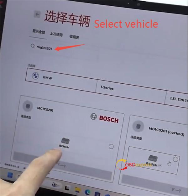
- Select the protocol tagged “(LOCKED)” on the right side of the interface.
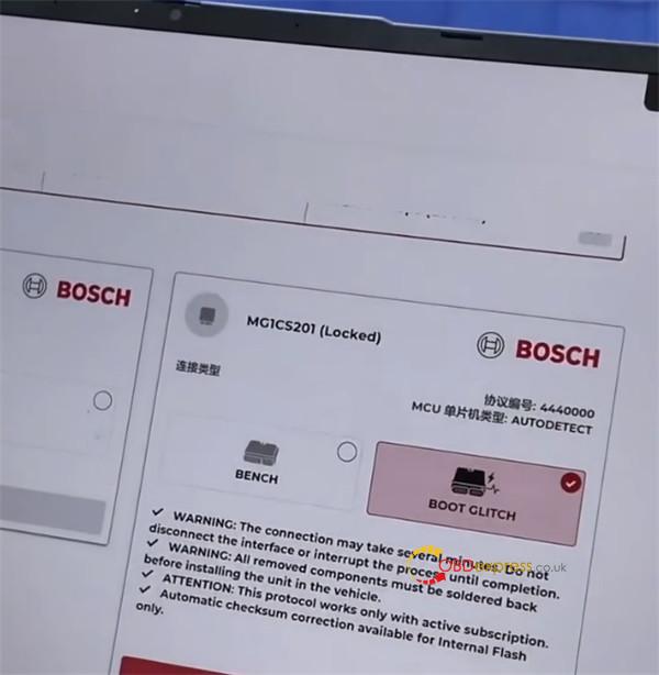
- Select Boot Mode (Direct Bench access will be rejected prior to Boot Glitch execution).
Step 2: Physical Connections & PCB Modifications
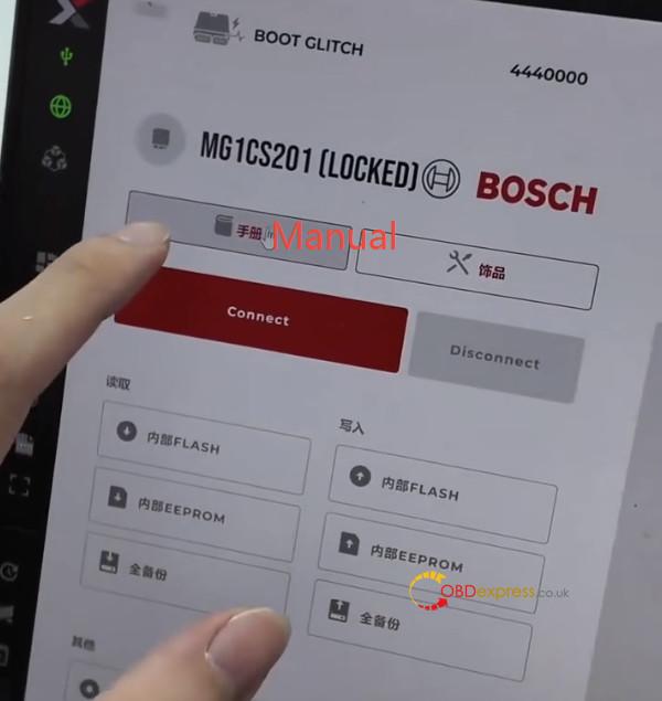
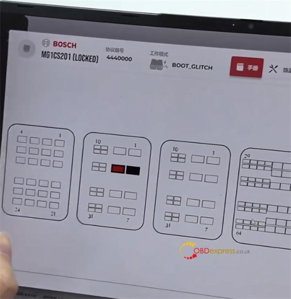
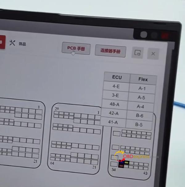
- Click Manual to open the circuit board wiring diagram.
- Connect power lines and CAN-H / CAN-L connections to the main connector.
- Remove the ECU’s top back cover to access the PCB.
- Verify engine type:
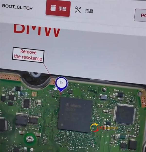
- B48 (MG1CS201): Follow Mini/BMW B48 PCB layout for E1 and resistor locations.
- B58 (MG1CS024): Follow B58 PCB layout for E1 and resistor locations.
- Mandatory Action: Desolder and remove the designated tiny SMD resistor on the PCB.
- Solder the E1 wire to the specified pad.
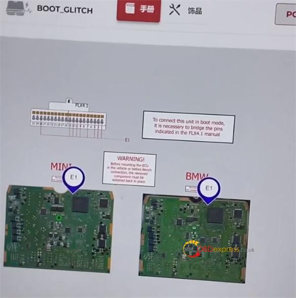
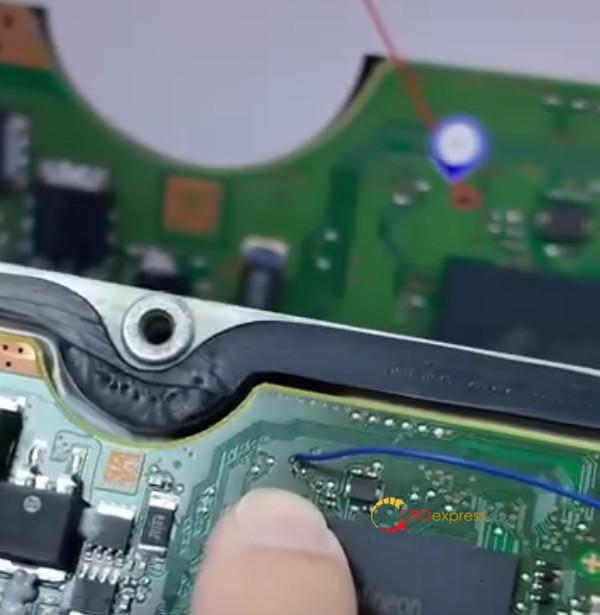
- Connect the wire harness to FLEX Port E (using pins such as 15 and 28 as indicated) and bridge the lead to the soldered E1 point.
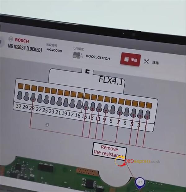
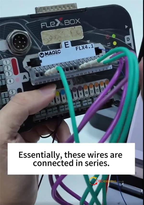
Step 3: Software Execution & Unlocking Sequence
- Click Connect to establish communication with the ECU.
- Read and save a full backup of the ECU data (Internal Flash / EEPROM).
- Run the Unlock function (executes BOOT GLITCH protocol 4440000).
- Wait for successful verification.
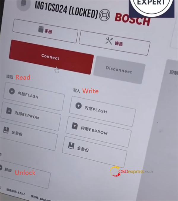
Step 4: Post-Unlock Bench Operation
- Disconnect Boot wiring and re-solder the original SMD resistor back into its slot.
- Seal the ECU casing.
- Reconnect using Bench Mode for seamless OBD/Bench read and write operations.
Safety Warnings & Constraints
CRITICAL OPERATIONAL RULES:
- Component Reinstatement: Never reinstall or run the ECU in the vehicle without resoldering the removed SMD resistor.
- Power Stability: Do not disconnect power or interface cables during the multi-minute Boot Glitch cycle.
- Protocol Requirements: Online execution requires an active FLEX subscription. Automatic checksum correction is supported for Internal Flash memory only.
(Visited 206 times, 1 visits today)
