


BDM100 programmer is verified to work no issues with Delphi ECUs including:
Delphi ECUs
Delphi DCM3.2 ECUs
Delphi DCM3.x (MB Version)
In detail…
Delphi ECUs
In case of a Delphi ECU the powerdistribution cannot be provided by special
pads of the BDM port.
Use separate wires to connect GND and+12Vcc to the pins of the main connector
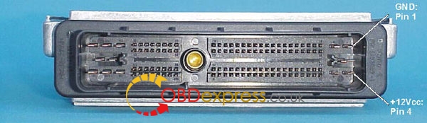
(The main connector of the Delphi ECU)
The voltage is provided by a stabilizedpower supply or by the main connector ofthe ECU at the cable harness of the car.
Warning ! Please always remind, if theopen ECU is connected to the cableharness of the car, it is already connected tothe battery!
Please, ensure that the ignition isswitched off while plugging the connections!
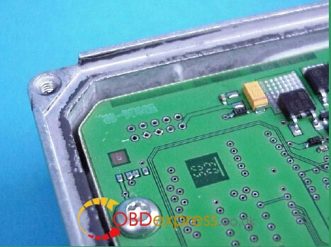
(The BDM pads of the Delphi ECU.)
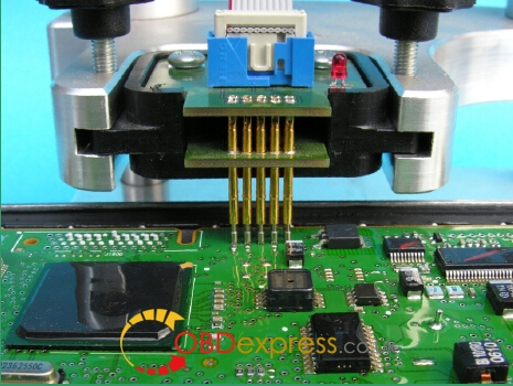
Now place the BDM142 probe into thepositioning frame and carefully put the tipsof the spring contact probes on the pads onthe board
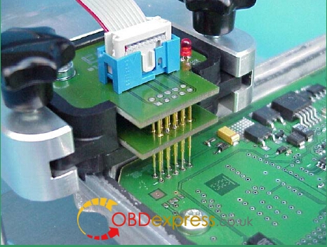
(The BDM142 probe contacting the BDMport pads of a Delphi ECU.)
The tips of the spring contact probes shouldreach a spring travel of 2mm minimum forbest contact conditions.
If you then applying power to the mainconnector of the ECU the red LED of theBDM142 probe lights up to indicate that thelogic on the board is supplied with therequired voltage.
Delphi DCM3.2 ECUs
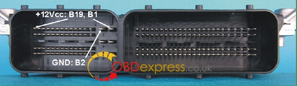
On the DCM3.2 the required contacts arelocated in the smaller chamber of the mainConnector
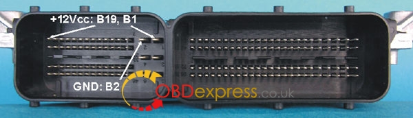
(The main connector of the Delphi DCM3.2 ECU.)
Use separate wires with matchingconnectors to connect GND and +12Vcc to
the pins of the main connector
(The main connector of the Delphi DCM3.2 ECU.)
Compared to the standard BDM pin out, thepin out of the BDM-pads on that board ismirrored, probably due the board wasprogrammed first in the factory beforemounting it into the case
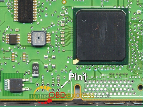
(The location of the required Pads.)
Now place a BDM147 probe into thepositioning frame and carefully put the tipsof the spring contact probes on the pads onthe board
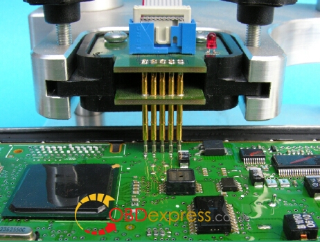
(Like that the BDM147 probe will bepositioned over the DCM3.2 board.)
The tips of the spring contact probes shouldreach a spring travel minimum of 2mm forbest contact conditions.
If you then applying power to the mainconnector of the ECU the red LED of theBDM147 probe lights up to indicate that thelogic on the board is supplied with therequired voltage.
The BDM100 module is now operational
Delphi DCM3.x (MB Version)
On the DCM3.2 the required contacts arelocated in the smaller chamber of the mainConnector
(The main connector of the Delphi DCM3.2 ECU from Daimler-Chrysler.)
Use separate wires with matchingconnectors to connect GND and +12Vcc to
the pins of the main connector
(The main connector of the Delphi DCM3.2 ECU from Daimler-Chrysler.)
The PCB-Layout of the DCM3.2 from MBdiffers slightly from the otherversions.
You have to close two jumpers first beforethis ECU is readable!
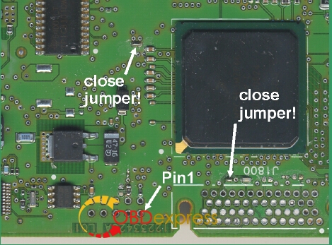
(The location of the BDM pads and the twojumpers you have to close first.)
Compared to the standard BDM pin out, thepin out of the BDM-pads on that board ismirrored, probably due the board wasprogrammed first in the factory beforemounting it into the case
(The location of the BDM pads and the twojumpers you have to close first.)
Now place a BDM147 probe into thepositioning frame and carefully put the tipsof the spring contact probes on the pads onthe board
(Like that the BDM147 probe will bepositioned over the DCM3.2 board.)
The tips of the spring contact probes shouldreach a spring travel minimum of 2mm forbest contact conditions.
If you then applying power to the mainconnector of the ECU the red LED of theBDM147 probe lights up to indicate that thelogic on the board is supplied with therequired voltage.
The BDM100 module is now operational.
