This is a GODIAG GT107+ DSG Plus Gearbox Adaptor user manual including ECU support list, connection diagram & operation steps, connection definition(pinout) and precautions.
GODIAG GT107+ DSG Plus Gearbox Supported ECU Models
Renault DC0/DC4 Gen2
Honda LUK UDCT
DQ200(0AM)[WR/CK]
DQ250C(02E)[RD/WR/CK]
DQ250E/F(02E)[WR/CK]
DQ200MQB/G2(0CW)[WR/CK]
DQ250MQB(0D9)[WR/CK]
VL300/V30(01J/0AN)[WR/CK]
VL381(0AW)[WR/CK]
DL501/G2(0B5)[WR/CK]
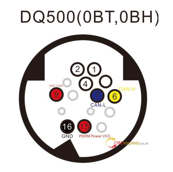
DQ500(0BH/0BT)[RD/WR/CK] reading when using a direct connection.
DQ200/MQB/G2 Boot(MICRO)[RD/WR/CK]
DQ200/MQB/G2 Boot(EEPROM)[RD/WR]
DQ250E/F/MQB Boot(MICRO)[RD/WR/CK]
DQ250E/F/MQB Boot(EERPOM)[RD/WR]
VL300/V30 BSL(FLASH)[RD/WR/CK]
VL300/V30 BSL(EEPROM)[RD/WR/CK]
VL381 Boot(MICRO)[RD/WR/CK]
VL381 Boot(EEPROM)[RD/WR]
DL501/G2 Boot(MICRO)[RD/WR/CK]
DL501/G2 Boot(EEPROM)[RD/WR]
Mercedes-Benz:
722.9—7G tronic
9GT(VGS-NAG3)
VGS(722.8)
BMW EGS 6HP
TEMIC DKG ZF 8HP Gearbox: BMW, JLR, VW/Audi, Rolls-Royce, Porsche, Bentley, Aston Martin, Lamborghini, Maserati, Dodge, Jeep, Chrysler, etc.
BMW 7-dual-clutch(GETAG 7DCT) Gearbox
DQ400
Connection Diagram & Operation Steps
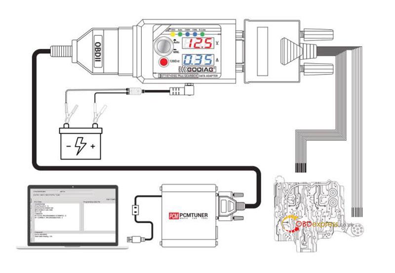
Maintenance Workshop Connection Diagram:
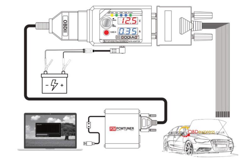
Car Connection Diagram
Operation Steps:
- Connect the GODIAG GT107+ to the gearbox ECU according to wiring definition. For VAG DQ250, DQ200, VL381, VL300, DQ500, DL501, for Renault DC0/DC4, Gen2, for Honda LUK UDCT.
- Connect the 12V 2A DC power supply(The function buttons must be popped up before connecting the power supply).
- GODIAG GT107+ analog ignition switch is in “automatic” mode if the ignition switch is not pressed. The voltage and current data of the adapter displays 0V 0A. And it is in “manual” mode if the ignition switch is pressed. The adapter displays the current working voltage of the power supply and current working current of gearbox ECU.
(Note: please select the “automatic” or “manual” analog ignition mode according to the mode required by the device for reading and writing data.)
- Connect PCMFlash, PCMTuner, J2534passthru.
- Perform data reading and writing operation.
Workshop Diagnostics or Other Equipment Manual Connection Operation
Manual ignition analog switch operation steps:
- Connect GODIAG GT107+ to the gearbox ECU according to wiring definition. For VAG DQ250, DQ200, VL381, VL300, DQ500, DL501, for Renault DC0/DC4, Gen2, for Honda LUK UDCT, Benz, BMW gearbox ECU.
- Connect the 12V 2A DC power supply(The function buttons must be popped up before connecting the power supply).
- GODIAG GT107+ analog ignition switch is in”manual” mode if the ignition switch is pressed. The adapter displays the current working voltage of the power supply and the current working current of gearbox ECU.
- Connect OBD2 data reading and wiring device or diagnostic device.
- Perform gearbox ECU data reading, writing or diagnostic operations.
Connection Definition
Gearbox ECU Interface Connection Definition
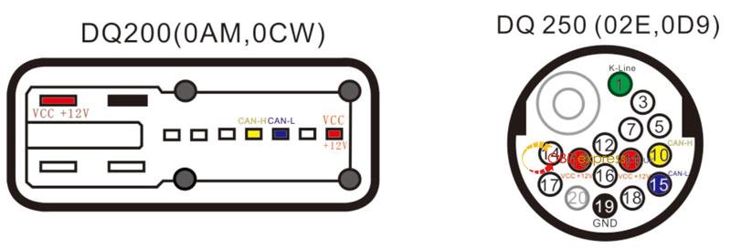
DQ200(0AM, 0CW), DQ250(02E, 0D9)
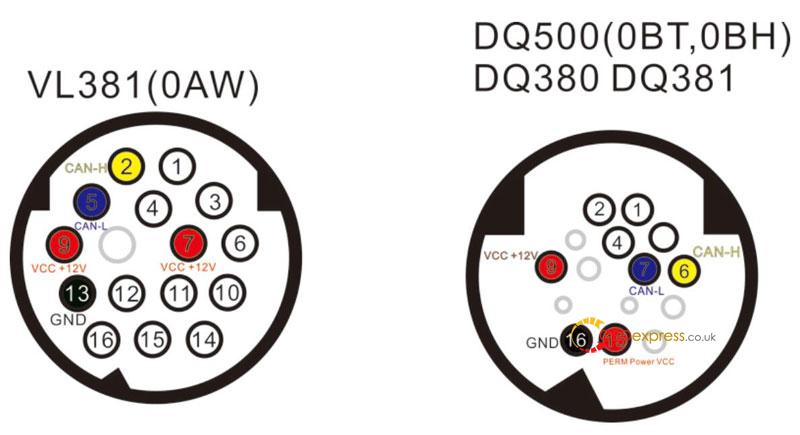
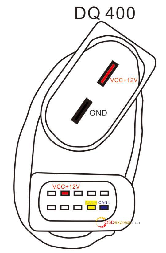
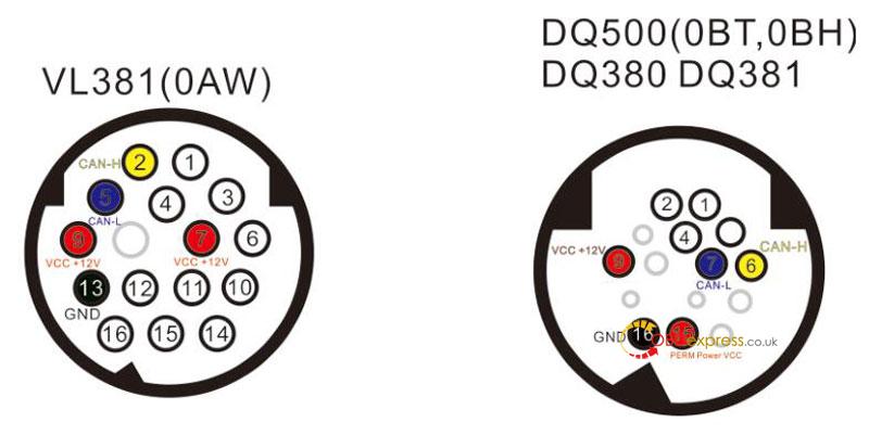
VL381(0AW), DQ500(0BT, 0BH), DQ380, DQ381, DQ400
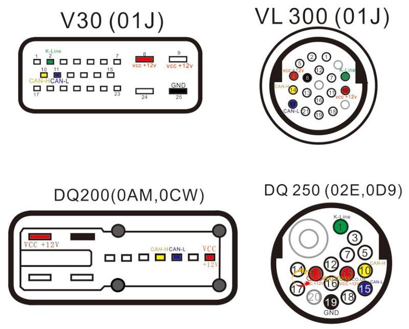
V30(01J), VL300(01J), DQ200(0AM, 0CW), DQ250(02E, 0D9), VL381(0AW), DQ500(0BT, 0BH), DQ380, DQ381
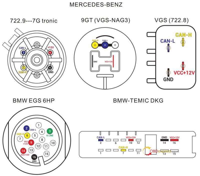
Mercedes-Benz:
722.9—7G tronic, 9GT(VGS-NAG3), VGS(722.8)
BMW EGS 6HP, BMW-TEMIC DKG
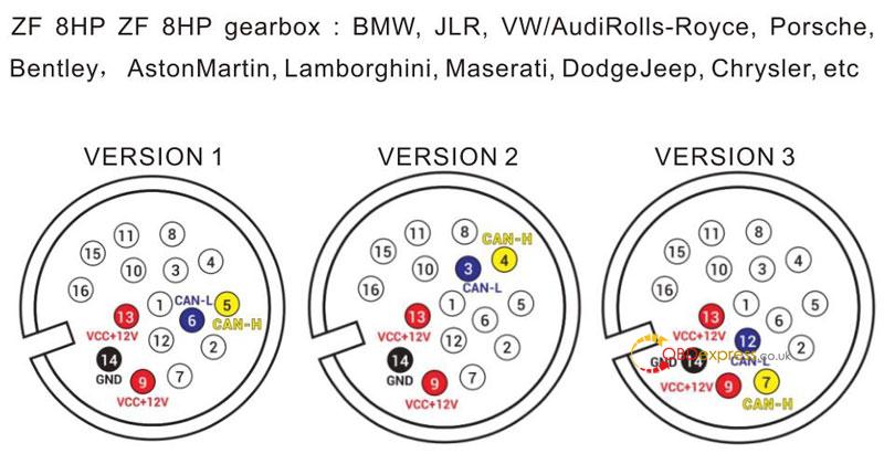
ZF 8HP ZF 8HP gearbox: BMW, JLR, VW/Audi, Rolls-Royce, Porsche, Bentley, Aston Martin, Lamborghini, Maserati, Dodge, Jeep, Chrysler, etc.
VERSON1, VERSION2, VERSION3
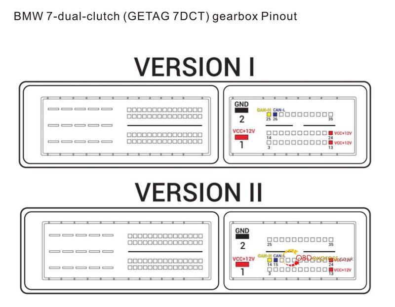
BMW 7-dual-clutch(GETAG 7DCT) gearbox Pinout
Precautions
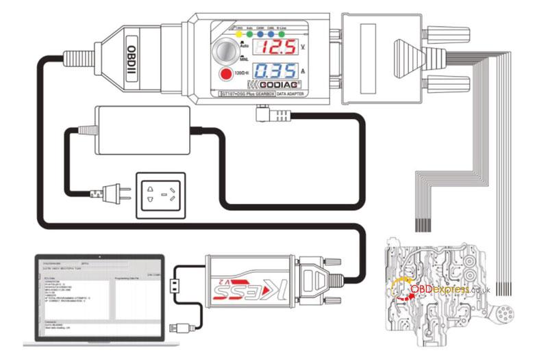
Precautions for PCMflash or PCMtuner flash to read and write DQ500:
Work BOOT: use a direct connection to the connector of the control UNIT, the switching power supply is carried out either manually(recommended) or by using the scheme of automatic power control. GODIAG GT107 DSG gearbox data adapter(same PowerBox or converted from KESS). In case of manual control, the entrance to the boot mode may not happen on the first attempt.
Read DQ500: only when connected directly!
Note: the power supply must be switched manually, while only the ignition must be switched on or off(pin 15), the second contact must be connected constantly.
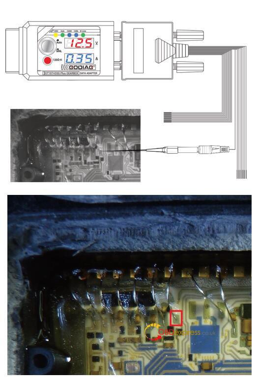
Operation in BSL with VL300/V30: requires drilling a single hole in the minimum diameter cap in order to insert a probe into it. The probe is connected to the GODIAG GT107+ DSG Gearbox Data Adapter BOOT 1k ohm GND line(included in the GT107+ host). it is mandatory to connect to-line and it is highly recommended to use auto power to quickly “feel” the pin on the board.
The pictures below show the drilling location and the point on the board where the probe should go.
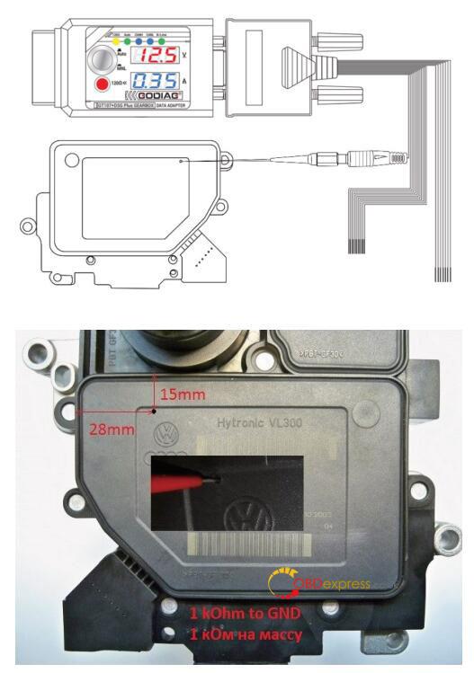
The connection pin picture after disassembling the ECU